|
|||||||||||||||||||||||||||||||||
|
Úvodní stránka
Obsah
Titulní list
Editorial
Aktualita
Doplněk X Aktualita
SOLARIMPULSE A Obsah AL2009
MacCready 2
Airfoils (Profily)
Vrtule
4 elektro větroně
Vzduchoplavecký podvečer
Knihy
AL na DVD
|
Airfoil characteristics
Airfoil characteristics - Charakteristiky profilů Pro procvičení, alespoň jak doufáme, v anglickém jazyce přinášíme článek o aerodynamických charakteristikách vybraných profilů všelikých tvarů a proto i vlastností. Ty jsou porozumitelné z jednotlivých grafů. Jsou zde uvedeny i jejich souřadnice. Pro ty kdo nejsou zběhlí v tomto jazyce je zde malý slovník použitých pojmů:
The first term, very often discussed, is the Reynolds number. It is a dimensionless criterion describing the relations at flowing around bodies. Two properties of air, its mass and its viscosity, determine the behaviour of the thin body layers over which the air flows. Viscosity could be roughly described as the stickiness and adhesiveness of the air and tends to keep the fluid in contact with surfaces. But it is the cause of the friction forces between the body surface and flowing fluid. The fluid mass and fluid velocities create the inertia forces of the flow. If the flowing fluid in the close distance of the body surface accelerates, the inertia forces increase. If it decelerates the inertia forces of the flow decreases. We can briefly say that friction forces have the negative effect and inertia forces have mostly the positive effect. Their result rivalry is explained by the Reynolds number. When the influence of the inertia forces (higher flow speeds and bigger airplane dimensions) predominates, the Reynolds numbers increase. The lift is higher and the drag is smaller. If the friction forces dominate, the Reynolds numbers decrease. The lift also decreases but the drag increases and it is not a good situation for flying.
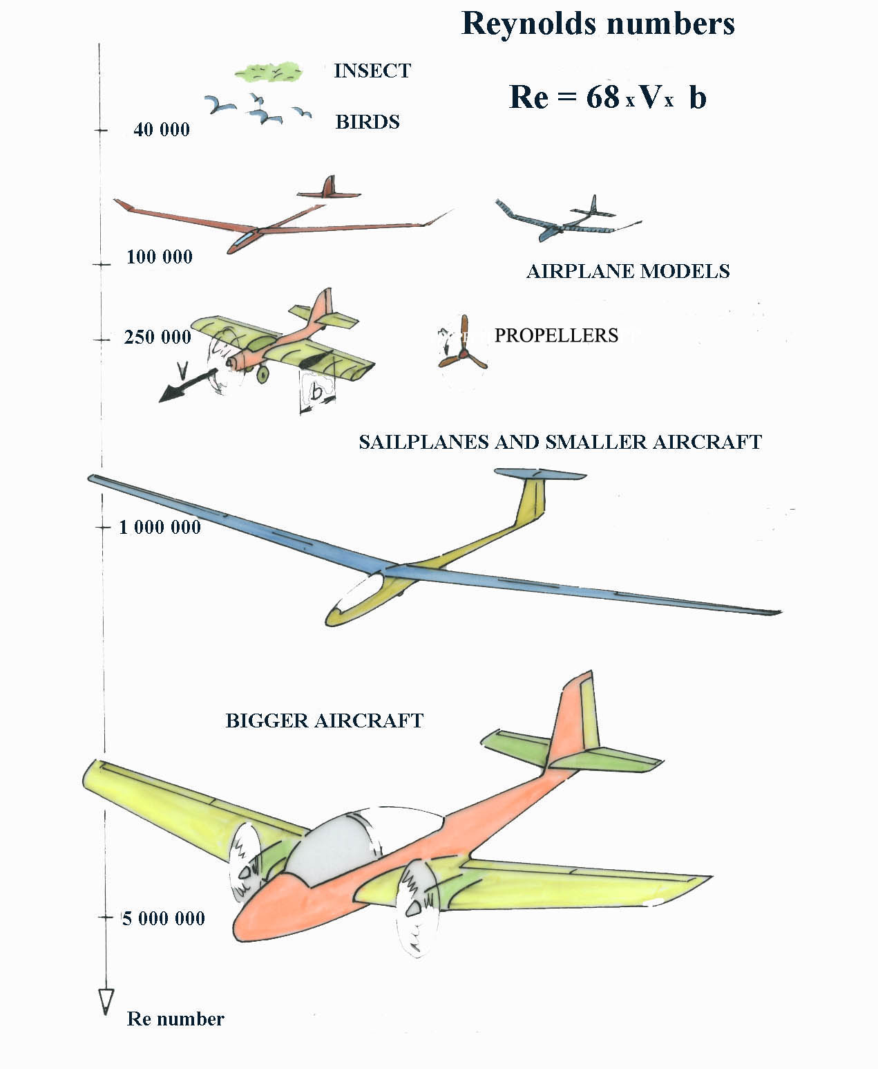
In Fig. No 8 there are shown examples of Reynolds numbers for some flying objects. There is also written, in the right hand corner, how to simply calculate Re number. Number 68 represents the mathematical constant concerning the air viscosity and is valid for low altitudes and temperatures between 15oC and 22oC. In winter the air is more favourable for models than in hot summer. Capital V is the flying speed expressed in m/s. Letter b is a characteristic dimension of the body which is the airfoil chord.
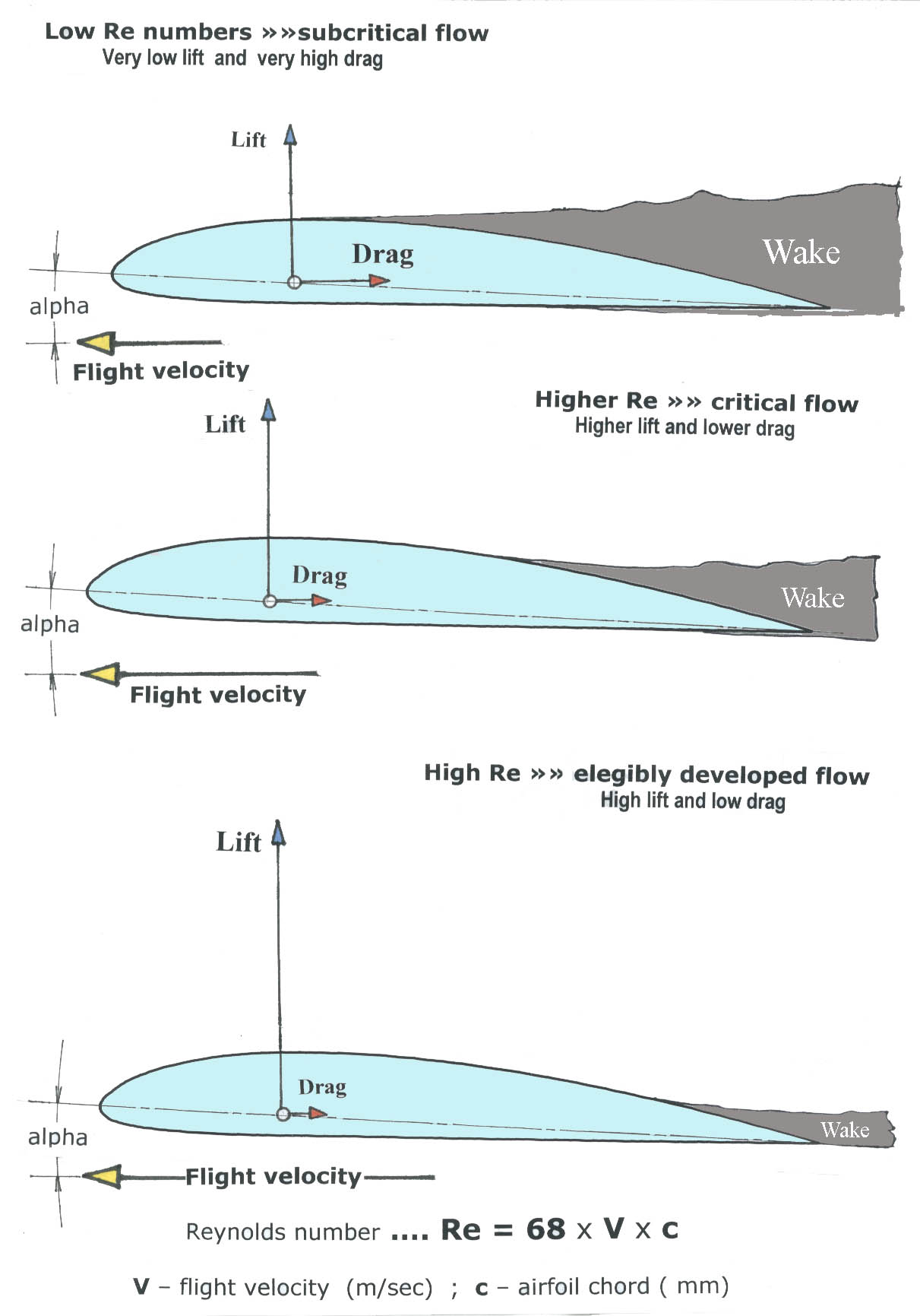
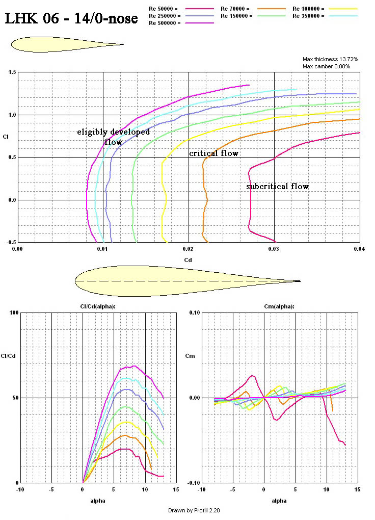
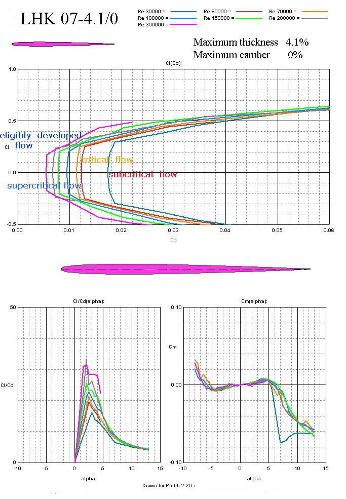
In Fig. No 9 there are shown three basic cases of the flow over the airfoil. The first one is the so called subcritical flow when the fluid abandons the wing surface very early and creates small lift and huge wake with high drag. The Reynolds numbers of this situation are usually lower than 45 000, when the thinner airfoils are used. The second one is a critical flow. The lift is higher and the drag smaller but the flowing over the wing or tail surfaces is not stable. Reynolds numbers of 20% thick airfoils are for example bigger than 100 000. The wake behind the airfoil is thinner but the flow properties are still not suitable for performance and reliable flight. The lowest picture shows an eligibly developed flow which creates good lift and small drag. This cause is called supercritical flow. And our wish is to reach it by all our designs. But it is not easy. Supercritical Re number values are usually higher than 75 000 for thin and not to much cambered airfoil. These values are for thicker airfoils bigger than 100 000. But for the well developed flowing we need more than 350 000. The Reynolds numbers range of flying models varies between 35 000 and 550 000. Experienced modelers know that the bigger model is, the better performances and flying properties has.
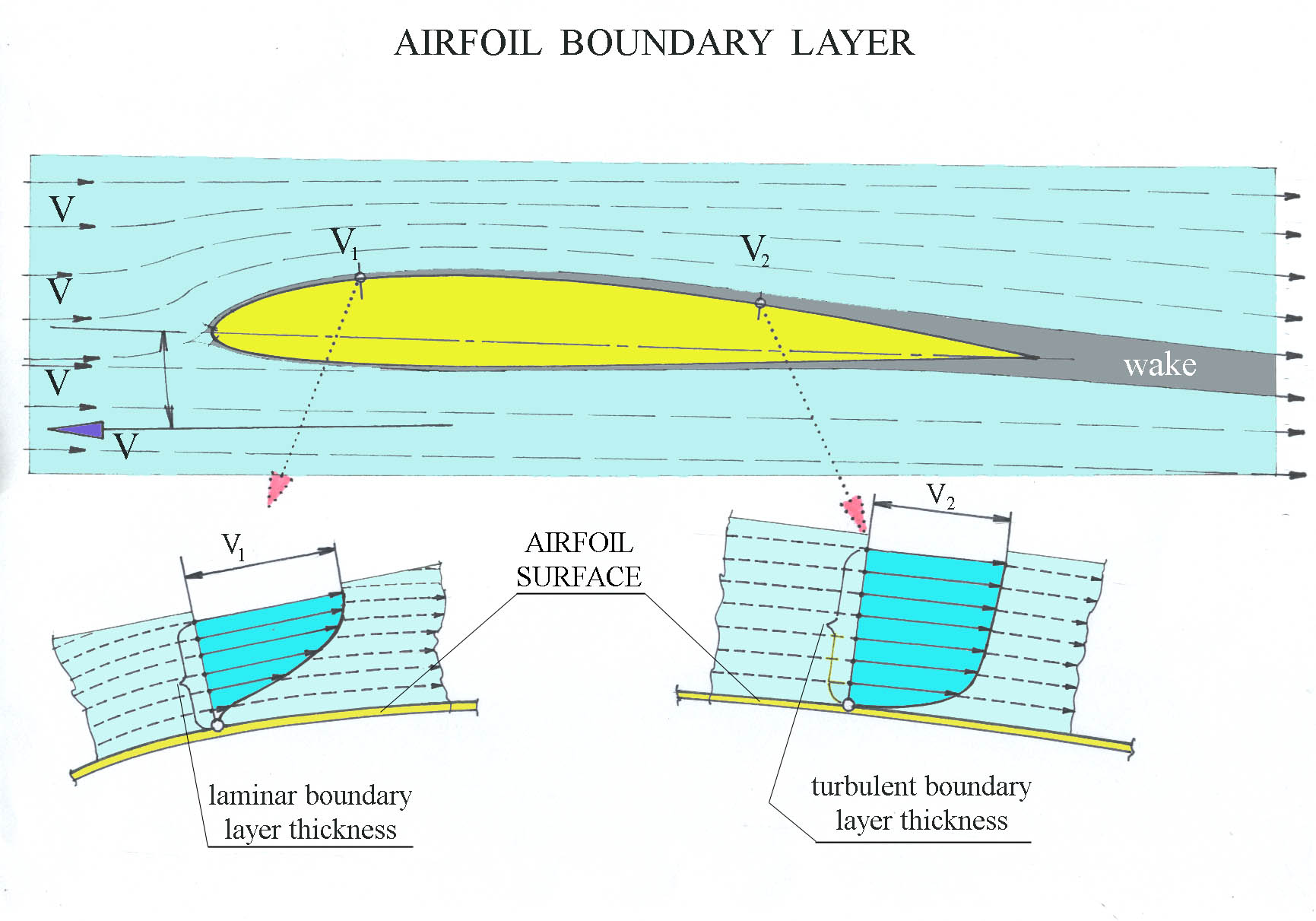
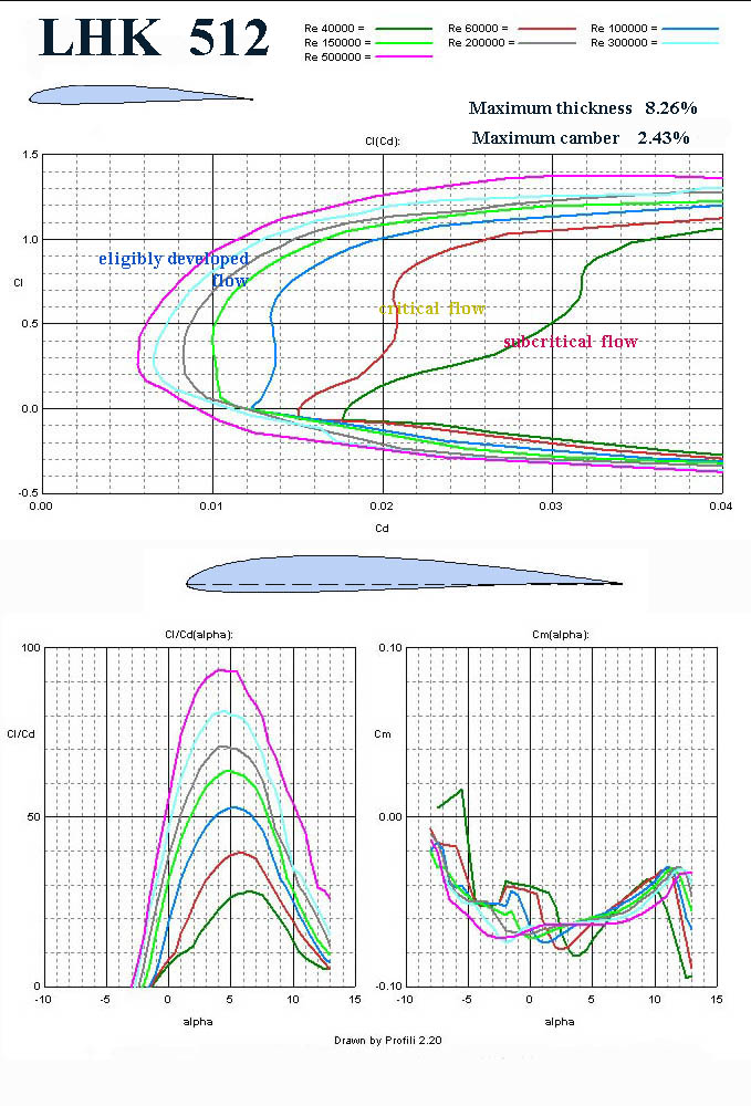
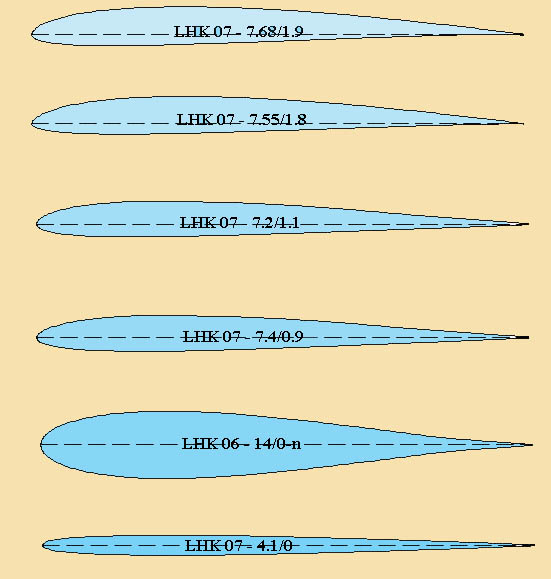
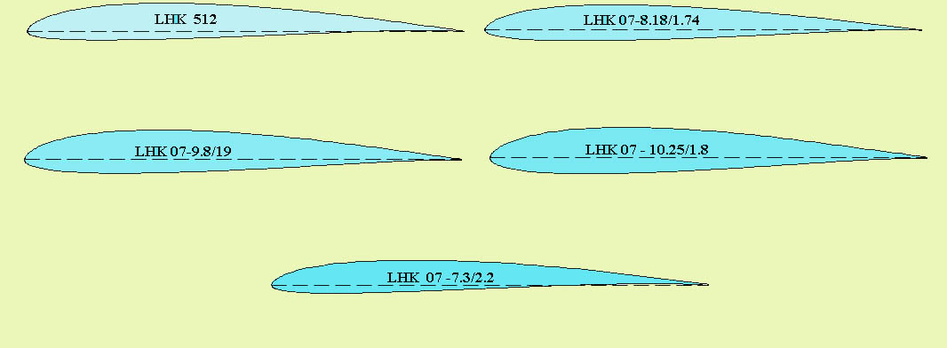
In Fig. No 10 there is shown a simplified flowing situation near the airfoil (wing of infinite span) surface. The viscous fluid, which the air is, creates two boundary layers on surfaces. There are very thin layers following each moving body in fluids in which the velocity changes from zero on the surface to the mainstream velocity at the point of the airfoil. Boundary layer thickness varies from tens of millimeter to one-two- three millimeters what depends on the surface roughness, waviness, form and the distance of the leading edge (point) at models. There are two distinct types of flowing in the boundary layers, laminar and turbulent. Laminar flowing has lower drag but is not stable. It has a tendency to separate the surface and create higher drag. The air particles moving in layers do not exchange the energy among them. So if a laminar flow has no right conditions to follow the surface as far as possible, separates and decreases lift dramatically and at the same time drag increases many times. The flying machine has many problems to continue in the flight. The turbulent flow has higher drag than the laminar flow but is much more stable and at sufficiently high Re number creates high lift and low drag. The air particles change their paths in boundary layer and so exchange their energy with each other. In this way are able to follow the surface shape further. The result is small wake and low drag. The transition of laminar flow to turbulent one does not come when Re number is so low that the flowing air particles are able to follow the surface, separate and create huge vortices. It is the former mentioned subcritical flow. If Re number little increases, the laminar flow has a tendency to transit into a turbulent flow. But this situation is not sufficiently stable and the lift and drag values change up and down quickly. It is the former mentioned critical flow. The flying performances and especially flying properties are inscrutable. When the transition of laminar to turbulent flow is reliable, and this case is our wish, the lift goes up and drag decreases continuously. The flow is eligibly developed, as I meant before. That is our victory and we have the possibility to fly very well. But for this situation we must create conditions. One of the important steps is the choice of an airfoil. Therefore I am bringing several airfoil characteristics created in computer to use the information for good and better decision of flying machine design and to avoid subcritical and critical flow over wings. The first one is in Fig. No 11. The airfoil LHK 512 can be used successfully on wide range of sailplanes. The chord on wing tips should not be smaller than 115 mm.
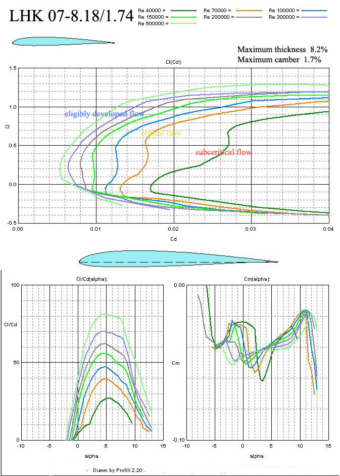
In Fig. No 12 there is LHK 07 – 8.18/1.74. It is an airfoil for F3B sailplanes, for example. The drag is low at very small lift coefficients, so these sailplanes will be able to fly very quickly at lower sinking speeds.
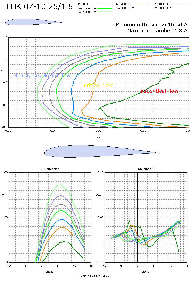
In Fig. No 13 there is an airfoil for the wing roots on sailplanes having higher aspect ratio, because its maximum thickness allows it. It is LHK 07 – 10.25/1.8. It can be also used in wings of air-combat machines.
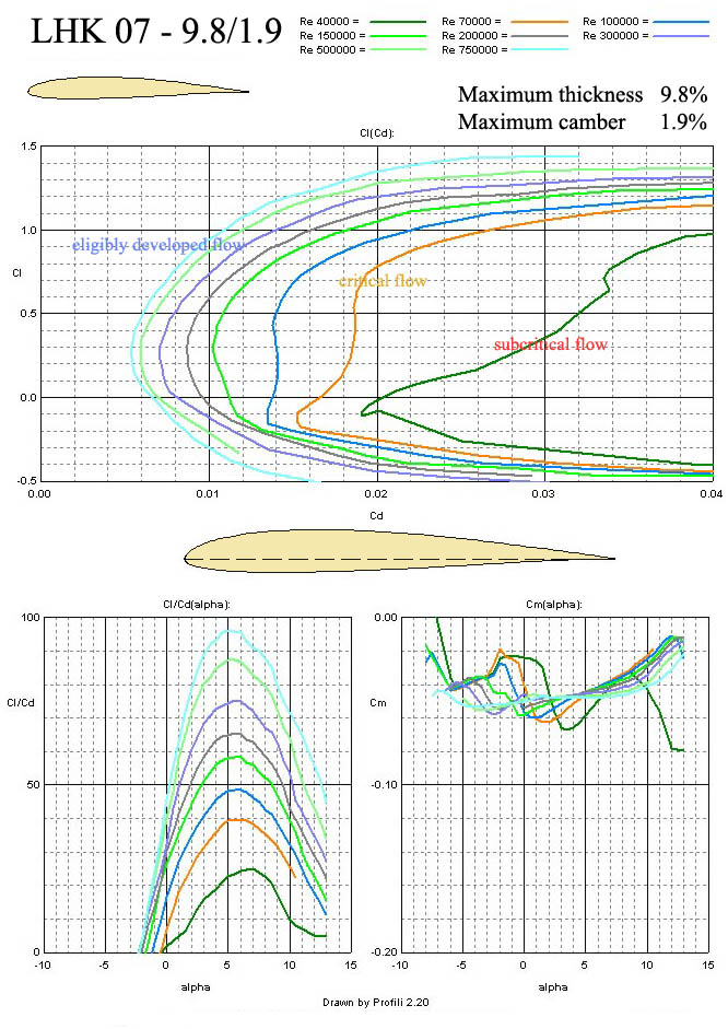
The thinner airfoil, with a little higher camber, LHK 07-9.8/1.9 is shown in Fig. No 14 is similar to the previous one. The combination of 10.25/1.8 on root and 9.8/1.9 on tip could be a good solution for great composite sailplanes.
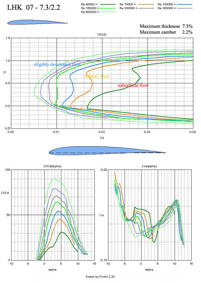
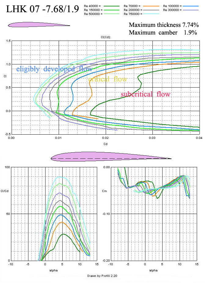
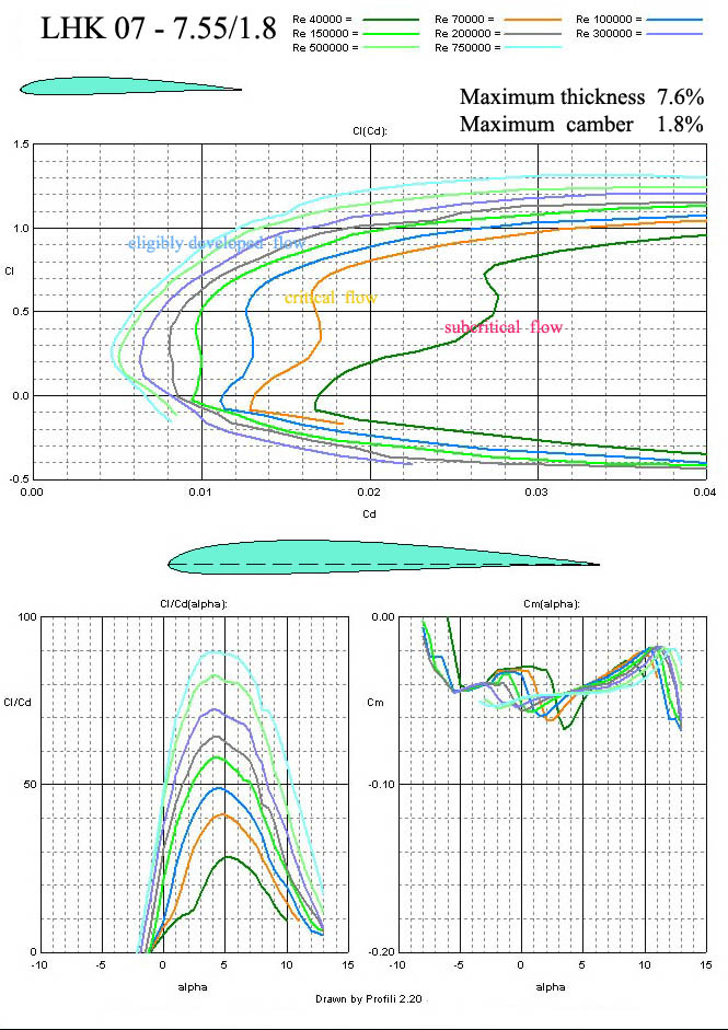
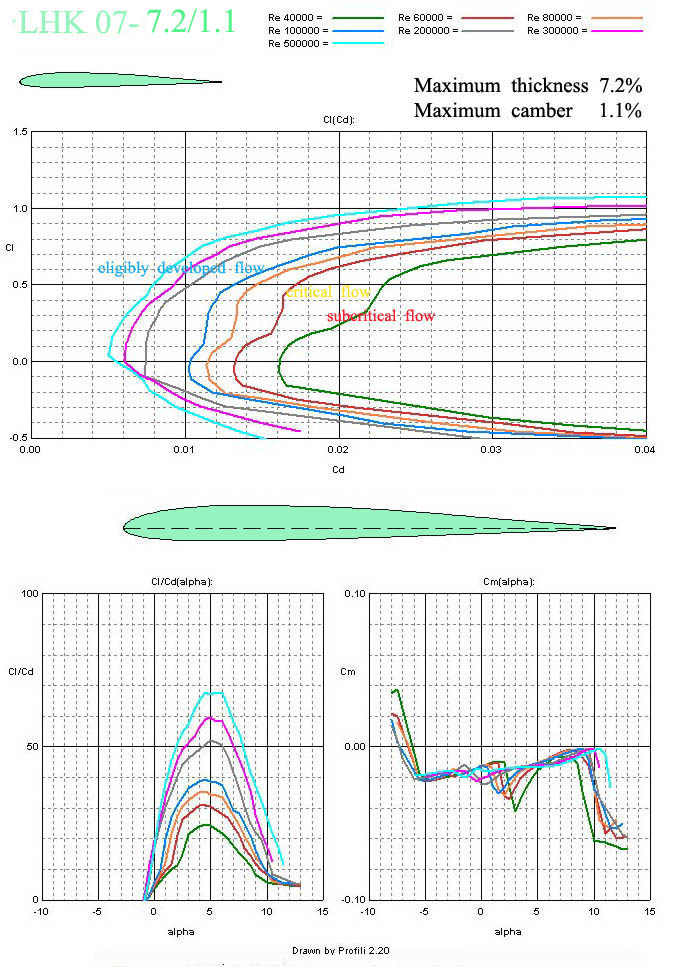
And now there are 4 airfoils which maximum thicknesses vary between 7.2% to 7.68% and the maximum camber is in the range of 1.1% to 2.2%. They are shown in Fig. No 15, 16, 17 and 18. Their application is among smaller and middle sailplanes with or without propulsion unit. The wing tip depths should be bigger than 100 mm.
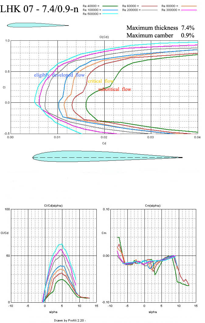
In Fig No 19 there is another thinner airfoil LHK 07 – 7.4/0.9 with low camber useable for wing roots of quick sailplanes or pylon racers. The best performances are in a good range of angle of attacks.
Two symmetrical airfoils are in Fig No 20 and 21. The first one LHK 06- 14/0-n is suitable for aerobatic models. The wing tip sections would be higher than 200 mm. LHK 07- 4.1/0 is a very thin airfoil designed for many flying stabs.
For all these airfoils their coordinates are enclosed. Not all of the airfoils published here were tested on models. But the design of all of them was based on our long-term experience.
Soubor se souřadnicemi profilů ke stažení: airfoils_data.zip Encl.: 14 figures, coordinates of 12 airfoils
Jaroslav Lněnička
1. 10. 2009
|
||||||||||||||||||||||||||||||||
| e-magazín Akademie letectví :: © Jan Janovec, © Jaroslav Lněnička :: akademie@airspace.cz | |||||||||||||||||||||||||||||||||